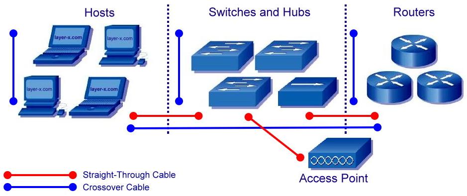
Straight-Through Cable - Four-pair, eight-wire, straight-through cable, which means that the color of wire on Pin 1 on one end of the cable is the same as that of Pin 1 on the other end. Pin 2 is the same as Pin 2, and so on. The cable is wired to either EIA/TIA T568B or T568A standards for 10BASE-T Ethernet, which determines what color wire is on each pin.
Crossover Cable - A crossover cable means that the second and third pairs on one end of the cable will be reversed on the other end. The pin-outs are T568A on one end and T568B on the other end. All 8 conductors (wires) should be terminated with RJ-45 modular connectors. Crossover cable conforms to the structured cabling standards. If the crossover cable is used between switches, it's considered to be part of the "vertical" cabling. Vertical cabling is also called backbone cabling. A crossover cable can be used as a backbone cable to connect two or more switches in a LAN, or to connect two isolated hosts to create a mini-LAN. This will allow the connection of two hosts or a server and a host without the need for a hub between them. This can be very helpful for testing and training. To connect more than two hosts, a switch is needed.
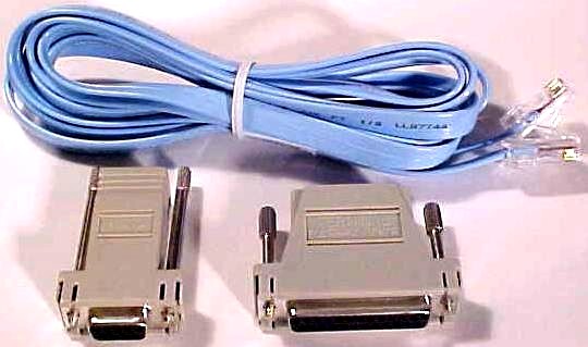
Rollover Cable - A 4-pair "rollover" cable. This type of cable is typically 3.05 m long but can be as long as 7.62 m. A rollover cable can be used to connect a host or dumb terminal to the console port on the back of a router or switch. Both ends of the cable have RJ-45 connectors on them. One end plugs directly into the RJ-45 console management port on the back of the router or switch. Plug the other end into an RJ-45-to-DB9 terminal adapter. This adapter converts the RJ-45 to a 9-pin female D connector for attachment to the PC or dumb terminal serial (COM) port. A DB25 terminal adapter is also available to connect with a PC or dumb terminal. This adapter uses a 25 pin connector. Figure 18 shows a rollover console cable kit.
 |
| Figure 18: Rollover Console Cable Kit |
Cable is called a rollover because the pins on one end are all reversed on the other end as though one end of the cable was rotated or rolled over. Figure 19 shows how to connect networking devices.
 |
| Figure 19: Connecting a Networking Devices |
 |
 |
 |